×
INDI Library v2.0.7 is Released (01 Apr 2024)
Bi-monthly release with minor bug fixes and improvements
Feature request: collimation assistant
- Alex Varakin
-
 Topic Author
- Offline
- Elite Member
-

- Posts: 174
- Thank you received: 27
Feature request: collimation assistant was created by Alex Varakin
I think it would be very nice to have a feature for assisting with the collimation, where the image preview screen would show corners of the image at 1:1 scale, so the user can see the quality of the stars in the corners all at once, without navigating the viewer.
Thanks
Alex
Thanks
Alex
2 years 7 months ago
#74730
Please Log in or Create an account to join the conversation.
- Hy Murveit
-
- Away
- Administrator
-

- Posts: 1220
- Thank you received: 565
Replied by Hy Murveit on topic Feature request: collimation assistant
A calibration assistant is definitely on my "want to do it someday, but may not ever get to it" list. Of course, I'd want to automatically evaluate the stars, and I'd want it to work for RCs, etc ") I know--keep it simple...
I know--keep it simple...
In the mean time, you may not be aware of something I added a couple of months ago, I believe released in 3.5.4, which might be helpful to you right now. If you hold down the control key while you mouse-over an image on the fitsviewer, you should see a 8X magnified version of the part of your image near the mouse (8X relative to what magnification is currently being display). You can, of course, keep holding down control and move the mouse around to different parts of the screen and the magnifying glass stays active. See this thread: indilib.org/forum/general/9737-fitsviewe...ing-glass.html#71615 which also show a picture of the magnifying glass in action.
Hy
I know--keep it simple...In the mean time, you may not be aware of something I added a couple of months ago, I believe released in 3.5.4, which might be helpful to you right now. If you hold down the control key while you mouse-over an image on the fitsviewer, you should see a 8X magnified version of the part of your image near the mouse (8X relative to what magnification is currently being display). You can, of course, keep holding down control and move the mouse around to different parts of the screen and the magnifying glass stays active. See this thread: indilib.org/forum/general/9737-fitsviewe...ing-glass.html#71615 which also show a picture of the magnifying glass in action.
Hy
2 years 7 months ago
#74733
Please Log in or Create an account to join the conversation.
- Alex Varakin
-
Topic Author
- Offline
- Elite Member
-
- Posts: 174
- Thank you received: 27
Replied by Alex Varakin on topic Feature request: collimation assistant
Hi Hy,
I was not aware about this feature, I will try it.
Here is the bible for collimating RC telescopes:
www.deepskyinstruments.com/truerc/docs/D...rocedure_Ver_1.0.pdf
and here is the image on page 14 that would be great to see in viewer in the collimation mode. Of course, the red lines would be difficult to produce and the numbers are redundant.
I think it would be nice to have some kind of a zooming control, where if it is 1, then the preview is as usual, but once you start increasing the value, the corners would be gradually magnified.
Alex
2 years 7 months ago
#74770
Please Log in or Create an account to join the conversation.
- Hy Murveit
-
- Away
- Administrator
-
- Posts: 1220
- Thank you received: 565
Replied by Hy Murveit on topic Feature request: collimation assistant
Agreed (about the bible). A friend and I have spent several nights in the past month using that guide to try and collimate an RC10. That's why I dream of making a semi-automated version of that collimation technique.
2 years 7 months ago
#74772
Please Log in or Create an account to join the conversation.
- Alex Varakin
-
Topic Author
- Offline
- Elite Member
-
- Posts: 174
- Thank you received: 27
Replied by Alex Varakin on topic Feature request: collimation assistant
Ah, sounds like there is no need to convince you ")
I think just showing the corners would be super helpful.
I think just showing the corners would be super helpful.
2 years 7 months ago
#74773
Please Log in or Create an account to join the conversation.
- Alex Varakin
-
Topic Author
- Offline
- Elite Member
-
- Posts: 174
- Thank you received: 27
Replied by Alex Varakin on topic Feature request: collimation assistant
I requested the same feature with CCDCiel and it was recently implemented.
2 years 6 months ago
#75914
Please Log in or Create an account to join the conversation.
Replied by Andrew on topic Feature request: collimation assistant
Ahhh. I Do Not recommend putting the DSI process into practice for the generic rebranded GSO Ritchey-Chretien telescopes commonly found on the market. They are constructed very differently, and the methodology does not translate well. It got me into a far worse condition that I ultimately recovered from through my own technique.
The issues start with the fact that they have a secondary mirror focus system and primary mirror tilt adjustments that does not disturb the alignment of the focuser.
So although their image balance methodology is ok for diagnosing any RC system. It is very difficult to use for making corrections in the field on generic RC scopes.
I could explain my collimation techniques in detail if people are interested. It requires no specialized tools, can be done on a tabletop setup and is extremely accurate.
2 years 6 months ago
#75948
Please Log in or Create an account to join the conversation.
- Hy Murveit
-
- Away
- Administrator
-
- Posts: 1220
- Thank you received: 565
Replied by Hy Murveit on topic Feature request: collimation assistant
Andrew,
I would really appreciate hearing more -- both about your technique, as well as about your reservations re DSI technique. Until hearing about your issues, I'd only heard great things about the DSI technique.
FWIW, I don't really understand your sentence: "BTW, The issues start..." sentence and am anxious to learn more.
As far as I can tell, the DSI technique worked well for me, but please explain further. I have a GSO RC10 truss--I got it second hand--I believe it's pretty close to this: www.highpointscientific.com/gso-10inch-r...oJ2Gc_UaAsQtEALw_wcB
FWIW, my OTA (and as far as I can tell similar OTAs from other vendors) doesn't come with a secondary focuser. However, the person I bought my OTA from did install the RainbowAstro RSF after-market secondary focuser: www.rainbowastro.com/rsf-2/ What I did need to do to get things working was (1) place my camera at the proper back-focus position and don't every move it from there, then (2) adjust the secondary focuser to gain focus, then (3) collimate using the DSI technique.
Hy
2 years 6 months ago
#75949
Please Log in or Create an account to join the conversation.
- Alex Varakin
-
Topic Author
- Offline
- Elite Member
-
- Posts: 174
- Thank you received: 27
Replied by Alex Varakin on topic Feature request: collimation assistant
I tried several different techniques for collimating my generic 8" and 10" RCs and DSI method was the best.
The only downside of it is that it has to be done at night, thus wasting precious imaging time.
The only downside of it is that it has to be done at night, thus wasting precious imaging time.
2 years 6 months ago
#75950
Please Log in or Create an account to join the conversation.
Replied by Andrew on topic Feature request: collimation assistant
The reason why secondary mirror focusing works is because the intermirror spacing changes the focal length. If the correct backfocus is known and the CCD is placed there, you will get well corrected and focused images when the spacing is correct.
The main issue I had with DSI is it is too subjective and you need calm air to do it. Couple that with focuser tilt when moving the primary on the GSO scopes, you end up not really sure where you end up and spend a great deal of time adjusting both the front and back on each step.
For reference I have an 8" RC steel tube, and no tilt-plate accessory.
My method in principle aims to align each main component in such a way that the mechanical interplay is no-longer a source of error. It can easily be done any time of day. I have verified the results by Star Tests, Howie-Glatter with holographic rings and a Ronchi test. All passed muster.
Step 0: The Setup
I like to position a DSLR behind the telescope on a Tripod with a zoom lens. The camera is connected to a laptop with me at the telescope so I can see the live view and control the focus while making adjustments. At no steps in the process does perfect alignment of the camera affect the judgment of adjustments needed in a significant way.
Step 1: Align the Secondary:
Traditionally you might think a cheshire eyepiece will work. But that is susceptible to focuser tilt error.
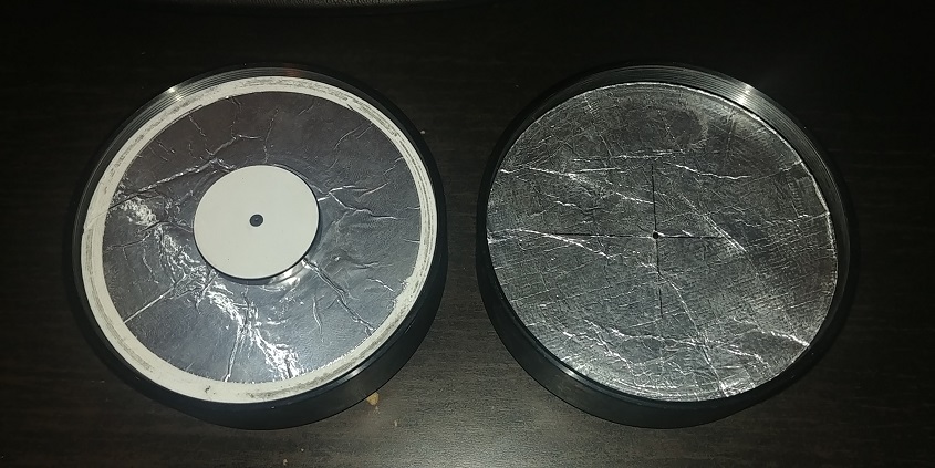
The solution is a collimation cap placed directly at the rear of the telescope with the focuser removed. I have two versions in the picture below. On the Right, my original foil on card stock and a 2mm peephole. On the left a 3D printed disk with the Howie Glatter laser 1mm knife-edge aperture mounted into it I made more recently.
Shine a lamp into the front of the telescope with paper to diffuse it to illuminate the interior. Next set the camera, zoom so the FOV covers the wide opening of the rear of the telescope. Adjust the exposure and focus on the center mark of the secondary. (Use live view zoom here, You will need the wider FOV for step 2.) Install the collimation cap and carefully reposition the camera to align it down the axis of the scope. Looking through the peephole with the correct zoom and focus you will see the center donut mark on the secondary and the shadow of the peephole.
Step 2: Align the Primary
Next remove the collimation cap. Adjust the exposure and focus. You should see the internal mirror surfaces, two views of the spider vanes and concentric rings of the internal baffles. Do not attempt to make the rings concentric. Any error on the camera's position will translate to an error of concentricity. Instead the goal is to align the two reflected views of the spider vanes. This view is true regardless of camera offaxis error.
When adjusting the primary, ONLY adjust 2 of the 3 screws. Reserve the 3rd for a final, minute adjustment if necessary. This way you limit the chance of changing the inter-mirror spacing.
Once the spider vanes are all perfectly in line. Congratulations! The telescope is now perfectly optically aligned!
Step 3: Focuser Tilt
Reinstall the focuser assembly. This step greatly benefits from having a tilt plate for adjustment. But there is play in the tilt of the stock crayford focuser before you lock the thread ring down.
At this point a laser collimator is useful. Take for granted that the secondary mirror is already perfectly adjusted, the laser should return directly when the focuser tilt is set to hit the center of the secondary mirror.
Conclusion:
Step 1 aligned secondary without concern for focuser misalignment.
Step 2 Optically aligned the primary with internal reflections
Step 3 Focuser tilt set without moving the primary or secondary mirrors.
Step 4: Optional spacing tuning.
As I mentioned before intermirror spacing is very important. If it is incorrect the focal length will change dramatically And coma will appear due to spherical aberrations.
When the mirrors are Too Close there will be Undercorrection. Too Far will introduce Overcorrection.
Focal length will shift by a factor of 1 to 10.
Example: Decreasing the distance between the mirrors by 1mm will increase the focal length by ~10mm
If you see coma and want to do Step 4, there are 2 acceptable ways to adjust the mirror spacing.
1: Adjust the center screw on the secondary mirror and re-do the secondary tilt adjustment.
2: Use the primary collimation screws to move the entire primary and realign the reflections.
3: There is a threaded locking ring on the secondary mirror baffle that may adjust the distance. But it might move the mirror off-center, so I would not recommend it.
All in all when you get used to this workflow it is very quick to do. Should take under an hour.
The main issue I had with DSI is it is too subjective and you need calm air to do it. Couple that with focuser tilt when moving the primary on the GSO scopes, you end up not really sure where you end up and spend a great deal of time adjusting both the front and back on each step.
For reference I have an 8" RC steel tube, and no tilt-plate accessory.
My method in principle aims to align each main component in such a way that the mechanical interplay is no-longer a source of error. It can easily be done any time of day. I have verified the results by Star Tests, Howie-Glatter with holographic rings and a Ronchi test. All passed muster.
Step 0: The Setup
I like to position a DSLR behind the telescope on a Tripod with a zoom lens. The camera is connected to a laptop with me at the telescope so I can see the live view and control the focus while making adjustments. At no steps in the process does perfect alignment of the camera affect the judgment of adjustments needed in a significant way.
Step 1: Align the Secondary:
Traditionally you might think a cheshire eyepiece will work. But that is susceptible to focuser tilt error.
The solution is a collimation cap placed directly at the rear of the telescope with the focuser removed. I have two versions in the picture below. On the Right, my original foil on card stock and a 2mm peephole. On the left a 3D printed disk with the Howie Glatter laser 1mm knife-edge aperture mounted into it I made more recently.
Shine a lamp into the front of the telescope with paper to diffuse it to illuminate the interior. Next set the camera, zoom so the FOV covers the wide opening of the rear of the telescope. Adjust the exposure and focus on the center mark of the secondary. (Use live view zoom here, You will need the wider FOV for step 2.) Install the collimation cap and carefully reposition the camera to align it down the axis of the scope. Looking through the peephole with the correct zoom and focus you will see the center donut mark on the secondary and the shadow of the peephole.
Step 2: Align the Primary
Next remove the collimation cap. Adjust the exposure and focus. You should see the internal mirror surfaces, two views of the spider vanes and concentric rings of the internal baffles. Do not attempt to make the rings concentric. Any error on the camera's position will translate to an error of concentricity. Instead the goal is to align the two reflected views of the spider vanes. This view is true regardless of camera offaxis error.
When adjusting the primary, ONLY adjust 2 of the 3 screws. Reserve the 3rd for a final, minute adjustment if necessary. This way you limit the chance of changing the inter-mirror spacing.
Once the spider vanes are all perfectly in line. Congratulations! The telescope is now perfectly optically aligned!
Step 3: Focuser Tilt
Reinstall the focuser assembly. This step greatly benefits from having a tilt plate for adjustment. But there is play in the tilt of the stock crayford focuser before you lock the thread ring down.
At this point a laser collimator is useful. Take for granted that the secondary mirror is already perfectly adjusted, the laser should return directly when the focuser tilt is set to hit the center of the secondary mirror.
Conclusion:
Step 1 aligned secondary without concern for focuser misalignment.
Step 2 Optically aligned the primary with internal reflections
Step 3 Focuser tilt set without moving the primary or secondary mirrors.
Step 4: Optional spacing tuning.
As I mentioned before intermirror spacing is very important. If it is incorrect the focal length will change dramatically And coma will appear due to spherical aberrations.
When the mirrors are Too Close there will be Undercorrection. Too Far will introduce Overcorrection.
Focal length will shift by a factor of 1 to 10.
Example: Decreasing the distance between the mirrors by 1mm will increase the focal length by ~10mm
If you see coma and want to do Step 4, there are 2 acceptable ways to adjust the mirror spacing.
1: Adjust the center screw on the secondary mirror and re-do the secondary tilt adjustment.
2: Use the primary collimation screws to move the entire primary and realign the reflections.
3: There is a threaded locking ring on the secondary mirror baffle that may adjust the distance. But it might move the mirror off-center, so I would not recommend it.
All in all when you get used to this workflow it is very quick to do. Should take under an hour.
The following user(s) said Thank You: Jim
2 years 6 months ago
#75953
Attachments:
Please Log in or Create an account to join the conversation.
Time to create page: 0.661 seconds
© 2003-2022 by INDI Library. All rights reserved.