×
INDI Library v2.0.7 is Released (01 Apr 2024)
Bi-monthly release with minor bug fixes and improvements
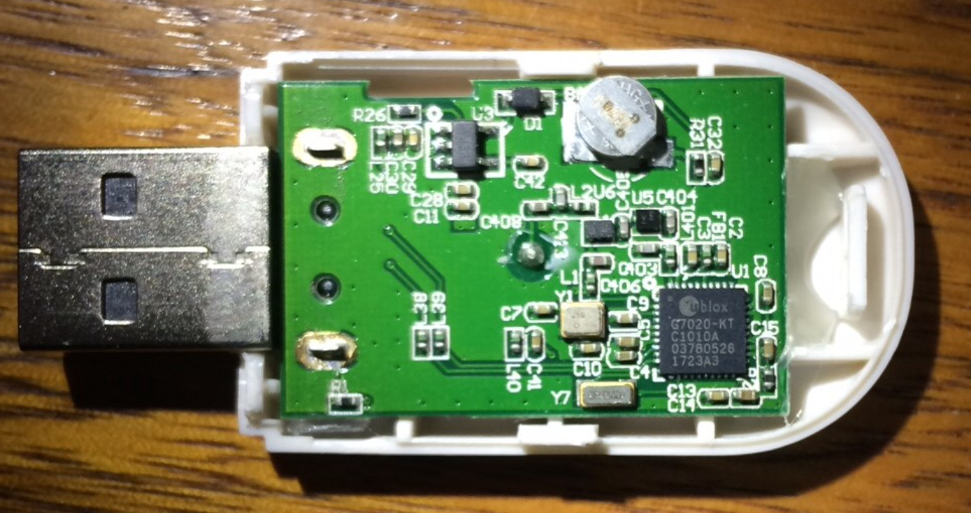
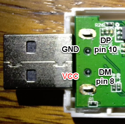
Fitting USB gps dongle inside rpi case...

")


Time to create page: 1.743 seconds
© 2003-2022 by INDI Library. All rights reserved.