- Details
- Written by Nacho Mas
INDIDUINO is a combination of hardware and drivers aims to fulfill miscellaneous automation functions on robotics telescope observatories. By mean of INDIDUINO boards and drivers you can switch on/off elements, obtain status and values from digital/analog inputs or event actuate servos.
Taken advantage of the great flexibility provide by both, arduino and INDI protocol, indiduino boards/drivers acquires its personality at runtime reading a xml files that define each arduino PIN behavior (Digital Input, digital output, PWM, Analog input). Thus is possible to make a plethora of hardware devices suitable for almost any propose.
The underlying technologies are Firmata, Arduino and INDI protocol. At this moment INDI platform is only available for Linux.
Indiduino is developed and maintained by Nacho Mas. For more up to date information visit INDIDUINO specialize site.
By default, the INDI INDUINO driver runs Simple Switcher skeleton. If you want to run another skeleton file, you must set the environment variable before running INDI server.
For example, to run INDUINO driver with stepper skeleton:
export INDISKEL=/usr/share/indi/stepper_sk.xml
indiserver -v indi_duino
- Details
- Written by Nacho Mas
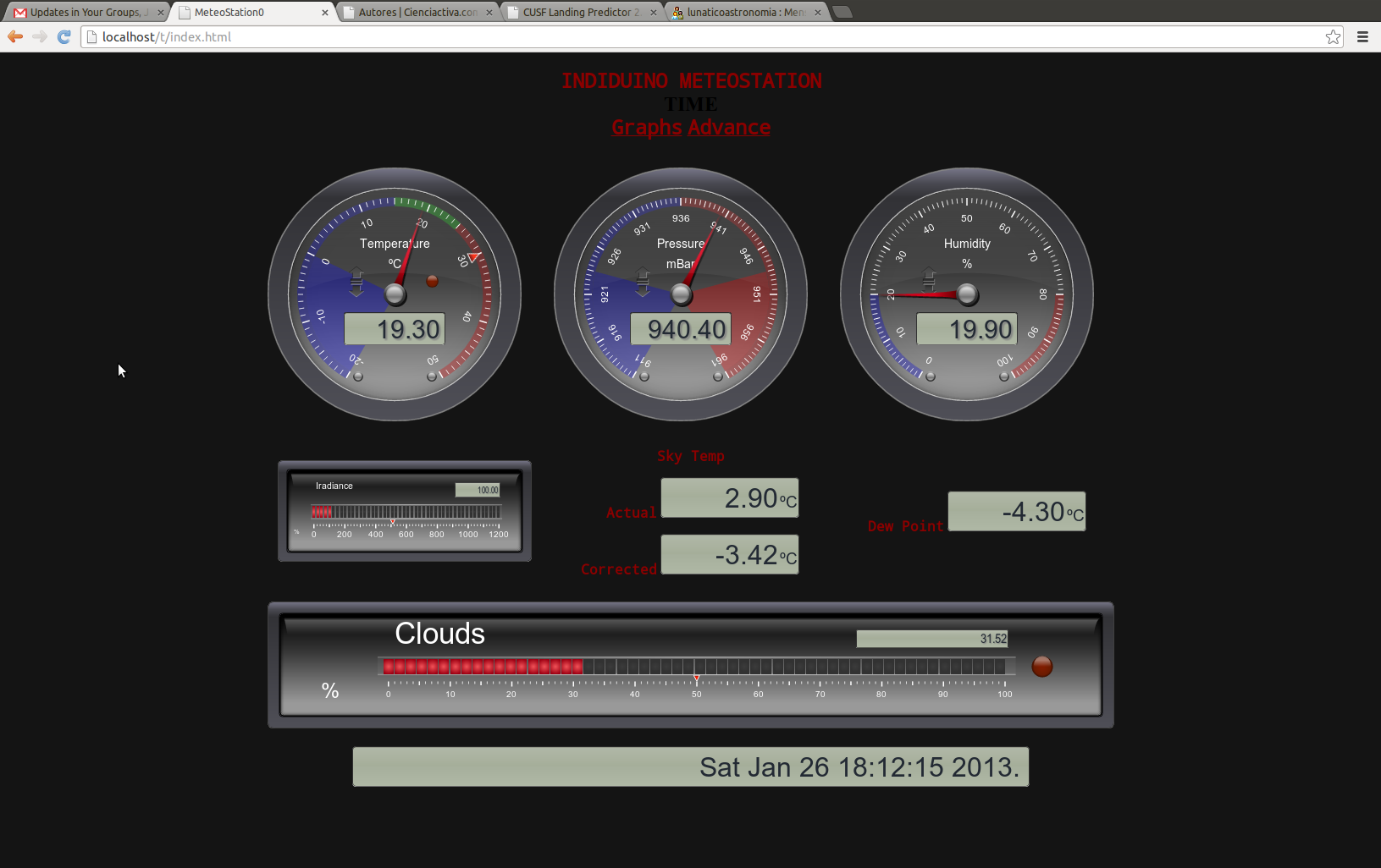
Every observatory need a meteostation thus here is the induino version!
Features:
- High precision barometer.
- Relative Humidity (HR) reading.
- Dewpoint calculation.
- Far sky temperature using Infrared Thermometer for determining cloud cover.
- Photocell to read sun radiance levels.
- One internal thermometer.
- Two external thermometer.
- Clouldy, dewing, freezing and daylight digital flag.
- Sensor malfunction flags.
- Web Interface with historical data.


Visit this page in Indiduino site for detail information
- Details
- Written by Nacho Mas
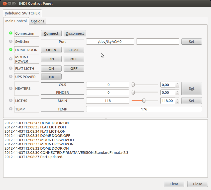
This is the easy one. Switch on/off your loads connecting your arduino board to a relay board like this one:

You can switch on/off up to 8 loads each within this limits AC 250V/10A or DC 30V/10A. Connect arduino pins from 2 to 8 to the relay board channels 1 to 8 and also VCC and GND arduino pins to VCC/GND pins
To install on your computer see How to Install Drivers
arduino firmware: StandardFirmata-2.3
skeleton file: switcher_sk.xml

Customize your device editing skeleton file and change "SOCKET 0X" for the real name of the device plugin
- Details
- Written by Nacho Mas
Read up to 12 digital inputs.
Adapting electronic is not need if the inputs are already TTL (0V->OFF, 5V-ON). If its not the case add additional circuits as needed.

To install on your computer see How to Install Drivers
Arduino firmware: StandardFirmata-2.3
skeleton file: digital_inputs_sk.xml
Customize your device editing skeleton file and change "INPUT 0" for the real name of the input plugin
- Details
- Written by Nacho Mas
Stepper
Controlling a stepper motor could be great for move several precision mechanical devices such focuser, filterwheel, etc.. In this example we use a modificated firmware for controling a stepper motor througth a EasyDriver Board.
First of all you have to flash your arduino with INDIDUINOStepper.ino firmaware. This firmware include some functions to cach the standard firmata behaviour and doing something more elaborated. We also use a Arduino AccelStepper library called from this custom firmware, thus it must be installed on your system.
Then connect the easyDriver to the VCC/GND and the coils of your stepper. Read EasyDriver documentation to do this. Finally connect arduino pins to the easydriver control signals in this way:
- pin 9 -> steps
- pin 8 -> dir
- pin 7 -> sleep


Arduino firmware: INDUINOStepper-2.3
skeleton file: stepper_sk.xml