
This looks fantastic!
Here's a pic of my Indi/Kstars RPi box, which I mount on top of my scope:
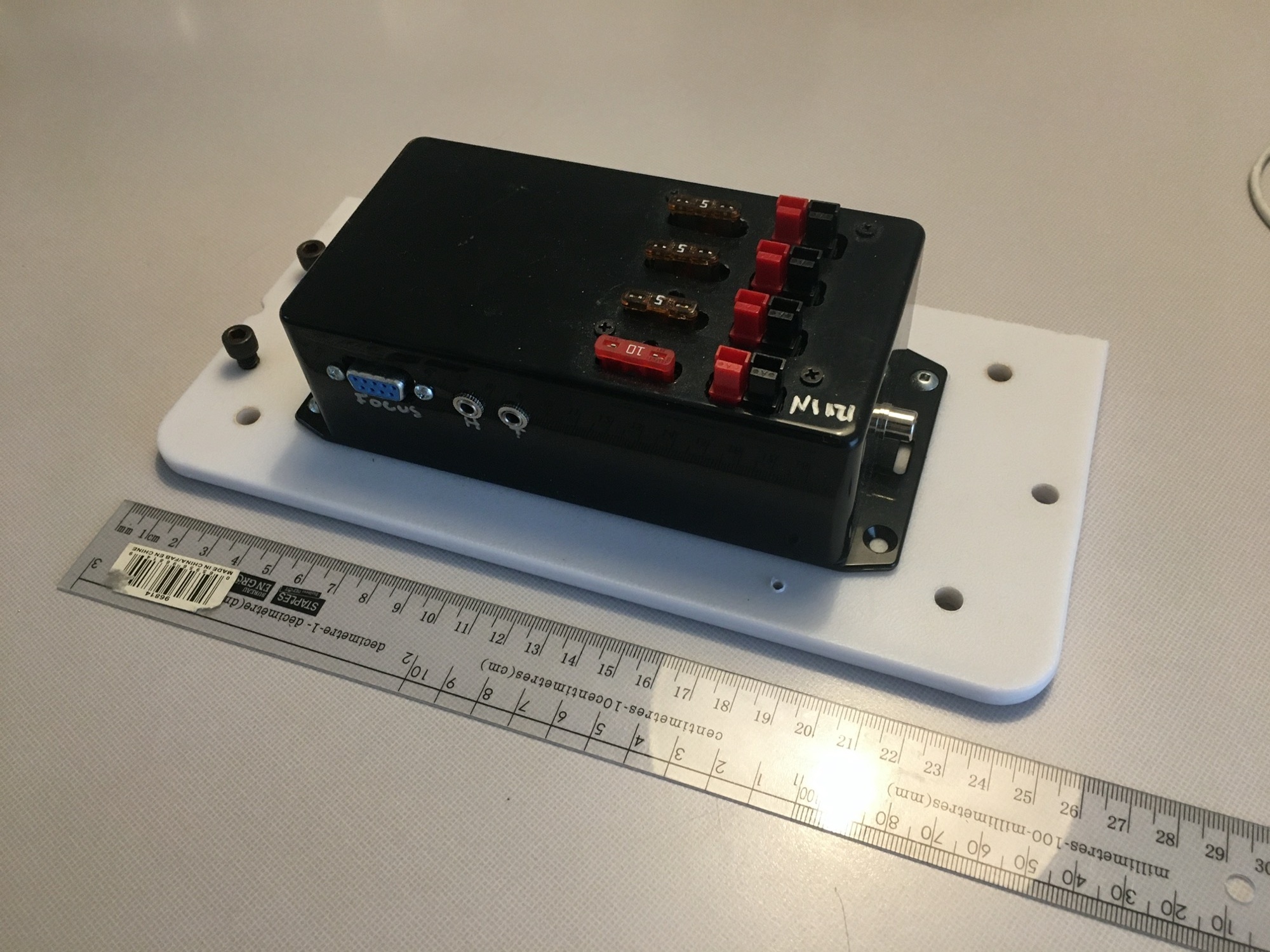
On the left side of the box as pictured is an Raspberry Pi 3B+ with an Adafruit motor hat. On the right side on top is a little Anderson power pole power distribution box and below a little breadboard with a circuit for a dew heater. The my RPi has the following interfaces:
- 1x12V (or whatever-it's pass through) input (Anderson Powerpole)
- For my setup, there is only one cable from the ground to my scope: 12V power. My goal is to minimize the number of cables running up my mount to my scope so I put the RPi on top of my mount. I power my mount from a separate power supply so there's no need to run power down from my RPi to the mount. I interface my RPi to the mount via bluetooth.
- 3x12V (pass through) outputs (Anderson Powerpoles)
- One of these powers my SBIG ST-8300M camera and another powers my RPi via a 12V to 5V 3A converter. I'd like to figure out a way to power the RPi internal to the project box but haven't done that yet.
- 1x12V RCA jack driven by my little dew heater circuit.
- 1x3.5mm jack for a humidity/temp sensor
- Used to calculate the dew point for my dew heater. Can also use ambient temp for focuser temp compensation.
- 1x3.5mm jack to read the OTA temp
- Allows for closed loop temperature control of the dew heater. I've written a little python script for this.
- 4xUSB ports of the RPi for my imaging camera, guide camera, GPS, and a 64GB thumb drive for images
- 1xD-sub 9 connector for my focuser (driven by the Adafruit Motor Hat)
So I think you've got everything I've got and more except a separate temp sensor input for sensing the OTA temp and a focuser. Are there any left over GPIO pins so that an OTA temp sensor could be used? I think an Adafruit motor hat could be mounted on top of your board but it'd need to get 12V power somehow and the I2C address would need to be changed if your board is using I2C.
Great project.
Steve
Read More...
© 2003-2022 by INDI Library. All rights reserved.