INDI Library v2.0.7 is Released (01 Apr 2024)
Bi-monthly release with minor bug fixes and improvements
Optimal Sub-Exposure Calculator help
Replied by Duccio on topic Optimal Sub-Exposure Calculator help
I try to click on clock icon but Kstar crash ad it close.
Please Log in or Create an account to join the conversation.
- Joseph McGee
-

- Offline
- Senior Member
-

- Posts: 42
- Thank you received: 11
Replied by Joseph McGee on topic Optimal Sub-Exposure Calculator help
Can you enable the logging, and attach the log output file?
Open Ekos, and click the Logs button. Set to Verbose and Output to File. In the Ekos section check the "Capture" box.
Then go through the process you followed that caused the crash. Log files should get written to your local KStars/logs folder.
Thanks
Please Log in or Create an account to join the conversation.
- Joseph McGee
-
- Offline
- Senior Member
-
- Posts: 42
- Thank you received: 11
Replied by Joseph McGee on topic Optimal Sub-Exposure Calculator help
When you bring up the EKos capture tab, what camera is appearing?
I was able to cause a crash when I used a profile that had a camera manufacturer selected (in this case ZWO), but I did not have the camera attached. In this case, the Indi control panel opened, but it had no tab for a camera. The Ekos Capture tab was available, but no camera was shown.
When the Exposure Calculator is launched it attempts to determine which camera is active so that it can try to find the proper read-noise data file. So the crash is likely happening because no camera data is available in EKos. I was also able to cause a crash in the Ekos capture screen by attempting to capture an image when there was no camera selected.
Please Log in or Create an account to join the conversation.
- Joseph McGee
-
- Offline
- Senior Member
-
- Posts: 42
- Thank you received: 11
Replied by Joseph McGee on topic Optimal Sub-Exposure Calculator help
The reason being is that the updated version of the exposure calculator now has the ability to directly download camera files from the github repository. The intent of the change is to allow users to better manage what camera files appear in the exposure calculator camera selector drop-down. But downloaded camera files will be stored user s home .local/share/kstars/cameradata folder. This means that a download of a file from github would potentially overwrite an identically named file in that folder.
Please Log in or Create an account to join the conversation.
- Joseph McGee
-
- Offline
- Senior Member
-
- Posts: 42
- Thank you received: 11
Replied by Joseph McGee on topic Optimal Sub-Exposure Calculator help
Last Summer I worked on a tool to calculate read noise for a camera to be used as input data for the exposure calculator. My results were not matching expectations so I set that project aside. But a few weeks ago I had time to re-visit this project. I found that the problem was not caused by my implementation of the calculations, but was actually caused by poor quality flat images which are used as inputs to the process.
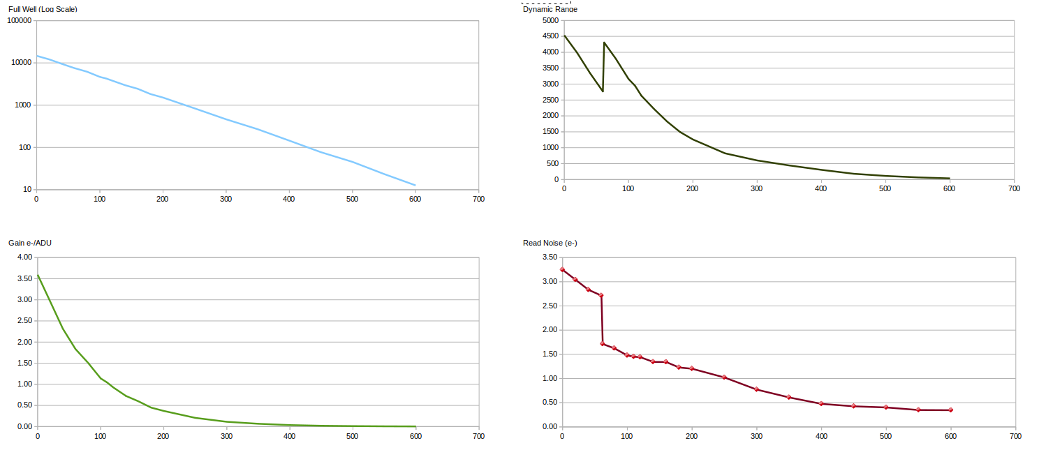
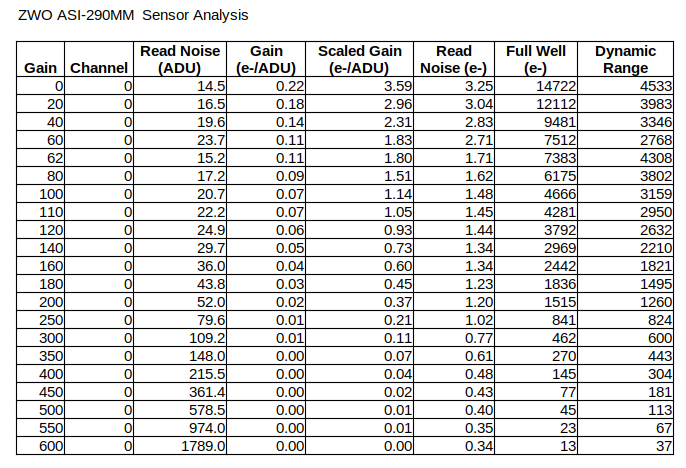
At this stage of development; this tool only reads the necessary fits input files and produces a table of data. I then move that table to a spreadsheet to produce graphs. The results I'm seeing in my tests cases match the camera documentation fairly well, but my tests are limited to data from just my three ZWO cameras. See attached examples from my analysis of my ZWO guide camera.
In an email exchange with Jasem, he suggested that I seek additional input files from folks on this forum. I'd be very interested to get files for cameras from other manufacturers, (and I'm particularly curious to see data from a CCD camera).
So, I'm looking for a few folks who are interested in this subject, and are willing provide me with some fits files from their cameras. This may be an iterative process, as I may need to adapt my process. If you are interested in helping please read on.
What my tool needs for CMOS cameras is a set of two bias images and two flat images for each gain/iso setting that is to be plotted. For a CCD camera there would only be a single set of images.
The interval on the gain/iso selections does not need to be constant. As you can see in the attached example data, I started with gain intervals of 20, but increased the interval to 50 when I was at higher gains (that I'm less interested in using). On my ASI-290MM, my initial tests showed the step in read noise between 60 and 80, so I captured additional sets to isolate that.
The flat images should be taken with the camera only, (not through a scope). Try to make flat exposures that are about 1 second or longer, otherwise the process may not produce accurate results.
(Just to be clear, the issue I experienced last Summer was caused by my using an LED panel as a light source which was too bright, even on it's dimmest setting. This caused the exposure times for the flat images to be extremely short. These short flat frames were excessively noisy, and had very subtle banding artifacts. I believe that banding was caused a flicker in the LED light source probably from the pulse width modulated dimming circuit. So I now use a thick stack of white paper to dim the light source)
I might also need the digital to analog conversion bits value for the camera. I have not yet learned how to compute this from fits data.
So, if you are interested in helping me by providing some test data, please let me know. (If my process works, we can use the read noise data to build a custom camera file for the exposure calculator).
Thanks
Please Log in or Create an account to join the conversation.
- Richard Francis
-

- Offline
- Premium Member
-

- Posts: 146
- Thank you received: 16
Replied by Richard Francis on topic Optimal Sub-Exposure Calculator help
SBIG ST2000XM (CCD)
QSI 583wsg (CCD)
FLI Kepler KL4040 (sCMOS)
Moravia C5A-100M (CMOS)
So this should provide some additions to the database.
Cheers,
Richard
Please Log in or Create an account to join the conversation.
Replied by Vladimir on topic Optimal Sub-Exposure Calculator help
Please Log in or Create an account to join the conversation.
- Frederick Ruegsegger
-
- Offline
- Elite Member
-

- Posts: 211
- Thank you received: 30
Replied by Frederick Ruegsegger on topic Optimal Sub-Exposure Calculator help
ZWO ASI 6200MM Pro
ZWO ASI 6200MC Pro
ZWO ASI 178MC
ZWO ASI 290MM Mini
ZWO ASI 174MM Mini
Please Log in or Create an account to join the conversation.
- Joseph McGee
-
- Offline
- Senior Member
-
- Posts: 42
- Thank you received: 11
Replied by Joseph McGee on topic Optimal Sub-Exposure Calculator help
(I'm sorry for the delay in my reply; I was working on some performance improvements to the analyzer tool, and also trying to understand an anomaly I see when I process data from color sensors.)
But I've just created a folder on Google Drive that should be writable for anyone with this link.
drive.google.com/drive/folders/1nHlqDTHz...ofudq?usp=drive_link
I assume that Google drive will allow you to create sub-folders in this shared folder, so it would probably be best to create a "home" folder for yourself. And then upload zip files of your bias and flat images to that home folder.
If you plan to create new flats and bias images for this effort:
Remember that I will need two of each file type, (2 flats and 2 bias), for each gain value being plotted.
I use file naming format like this /%t/%T/%F/%t_%T_%F_Gain_%G_Offset_%O to help me distinguish the files. (But I can jut read the fits header if need be).
For flats I've been setting the calibration option for the ADU to 29000. But this is probably not critical, as long as the value you use is reasonable and consistent.
As I mentioned, I'm using a dimmable LED panel for my flats. But to reduce the brightness I ended up inserting about 30 sheets of printer paper between camera and the panel so that the exposure time for flats is around 1 second. But when I image at with higher gain values I've had to add a few more sheets of paper because the exposure time can fall rapidly at high gains.
I also found that my cameras leak light in quite badly. I've been creating my images in daytime, and find that I need to cover the camera with a dark cloth to avoid unwanted light in the exposure.
Thanks again for your help!
Please Log in or Create an account to join the conversation.
- Richard Francis
-
- Offline
- Premium Member
-
- Posts: 146
- Thank you received: 16
Replied by Richard Francis on topic Optimal Sub-Exposure Calculator help
I've added the curves I obtained to the Moravian folder in case they are useful. Please take note of the page from the user manual I added as well, which points out that the "gain" is a command to the driver and is not a multiplicative gain, neither in linear or dB. The conversion from the 2 values I used to multiplicative gain is given there. I suspect this might be true for all Moravian CMOS cameras, by the way.
For the QSI I also made a photon transfer curve, so I must have the data (without scope) somewhere. As I can't find them I have instead used the oldest (and best quality) through-the-scope flats I could find. If this is no good I can fish out the camera and make some more. Same story for the SBIG ST2000XM, except I never made a photon transfer curve.
I will rework the Kepler and QSI photon transfer data into the same form as the Moravian plots (easier to interpret) if you find them useful.
Cheers,
Richard
Please Log in or Create an account to join the conversation.
- Frederick Ruegsegger
-
- Offline
- Elite Member
-
- Posts: 211
- Thank you received: 30
Replied by Frederick Ruegsegger on topic Optimal Sub-Exposure Calculator help
Please Log in or Create an account to join the conversation.
- Joseph McGee
-
- Offline
- Senior Member
-
- Posts: 42
- Thank you received: 11
Replied by Joseph McGee on topic Optimal Sub-Exposure Calculator help
I was able to get the SBIG ST2000XM Data to process through my tool.
To be clear:
1) My tool only analyzes a 100x100 pixel region at the center of the sensor. (That's actually a recommend approach when performing this type of analysis).
2) The value shown for "Gain Scaled" has to do with adjusting the reported gain for the bit depth of the sensor vs the bit depth read from the fits file. So, for example, if the sensor were only 14 bits, then the Gain Scaled (e-/ADU) value would be 4 times the value reported as "Gain (e-/ADU)". (I'm working on a function that hope will detect the sensor bit depth by analyzing the intervals between pixel values, but that function is not yet active, so this output assumes the sensor is actually 16 bits).
Read Noise (ADU): 10.6161
Gain (e-/ADU): 0.6288
Gain Scaled (e-/ADU): 0.6288
Read Noise (e-): 6.6756
Full Well (e-): 41210.2823
Dynamic Range (Stop): 12.6351
After running this I looked up some specs on this camera, and the values my tool reports seem to be reasonable.
I will continue with testing on the other cameras.
Please Log in or Create an account to join the conversation.